-
HMMWV
-
-
- Fig. 2. Engine Mounting Brackets.
- Fig. 3. Engine Oil Dipstick and Tube Assembly.
- Fig. 4. Engine Oil Pan, Pump, and Filler Tube.
- Fig. 5. Engine and Transmission Oil Cooler and Lines.
- Fig. 6. Oil Filter, Adapter, and Oil Line Fittings.
- Fig. 7. Crankcase Depression Regulator Valve
- Fig. 8. Air Intake and Exhaust Manifolds.
-
- Fig. 10. Fuel Injection Pump and Fuel Filter Lines
- Fig. 11. Fuel Injector Supply and Return Lines
- Fig. 12. Air Cleaner, Air Horn, and Related Parts.
- Fig. 13. Fuel Tank Supply & Return Lines (Early Models)
- Fig. 14. Fuel Tank Supply & Return Lines (Current Models)
- Fig. 15. Fuel Tank Assembly, Basic & A1 Trucks
- Fig. 16. Fuel Tank Assembly, A2 Trucks
- Fig. 17. Fuel Filter Pipe Assembly and Vent Lines
- Fig. 18. Fuel Tank Vent Line, Filter, And Mounting Hardware
- Fig. 19. Fuel Filter, Water Separator And Mounting Hardware
- Fig. 21. Accelerator Controls And Hand Throttle.
- Fig. 22. Accelerator Cable Bracket And Idle Spring
- Fig. 9. Fuel Pump and Mounting Hardware.
-
- Fig. 26. Radiator And Mounting Hardware
- Fig. 27. Surge Tank And Related Parts
- Fig. 28. Radiator Shroud And Related Parts
- Fig. 29. Radiator Hoses And Related Parts
- Fig. 30. Thermostat, Water Crossover & Hardware
- Fig. 31. Water Pump & Hardware
- Fig. 33a. Idler Pulley, Tensioner, Parts (SN 196901 & Above)
- Fig. 33b. Idler Pulley, Tensioner, Parts (SN 196901 & Above)
- Fig. 34. Fan Drive And Pulley
-
- Fig. 35a. Generator, 60 AMP, Belts, Pulley, and Mounting Hardware (1 of 2)
- Fig. 35b. Generator,100 AMP, Belts, Pulley, and Mounting Hardware (2 of 2)
- Fig. 44. Starter Motor, Cable Assemblies, & Hardware
- Fig. 46. Instrument Panel Assembly & Mounting Hardware
- Fig. 47. Instrument Cluster Assembly
- Fig. 48. Circuit Breakers
- Fig. 49. Directional Unit, Protective Control Box, & Flasher
- Fig. 50. Transmission Control Module, Circuit Breaker, & Relay
- Fig. 51. Stoplight Switch, Time Delay & High Beam Switch
- Fig. 60. Front Composite Light And Mounting Hardware
- Fig. 61. Rear Composite Light and Mounting Hardware
- Fig. 62. Blackout Lamp And Headlight Assembly
- Fig. 63. Clearance Marker Light Assembly
- Fig. 66. Sending Units
- Fig. 66a. Fan Cut-Off, Throttle Position & Engine Speed Sensor
- Fig. 67. Fuel Pressure & Level, & Assorted Indicator Switches
- Fig. 68. Horn And Horn Button Assembly
- Fig. 69. Batteries,Cables,And Related Parts
- Fig. 71. Battery Mounting Components & Related Parts
- Fig. 83. Body Wiring Harness-Partial View
- Fig. 84. Body Wiring Harness-Partial View
- Fig. 85. Body Wiring Harness-Partial View
- Fig. 86-1. A2 Body Wiring Harness
- Fig. 86-2. A2 Body Wiring Harness
- Fig. 88-1. A2 Body Wiring Harness Installation
- Fig. 88-2. A2 Body Wiring Harness Installation
- Show all articles ( 11 ) Collapse Articles
-
- Fig. 100. Transmission Shift Controls And Modulator
- Fig. 101. Transmission Shift Lever, Shift Bracket,And Rod
- Fig. 103. Transmission Hardware, Dipstick & Tube Assembly
- Fig. 104. Transmission Assembly
- Fig. 105. Transmission Assembly
- Fig. 123. Transmission Vent Lines And Attaching Hardware
- Fig. 124. Transmission/Transfer Cooling Lines
- Fig. 125. Transmission/Transfer Cooling Lines
- Fig. 97. Transmission Shifting Components
- Fig. 98. Transmission Shift Control And Neutral Start Switch
- Fig. 99. Transmission Shift Control And Neutral Start Switch
-
- Fig. 128. Transfer Case Assembly, P/N 12340073-1
- Fig. 129. Transfer Case, 5937387, 12342643-1, & 12447125
- Fig. 130. Transfer Case, P/N 5937387,12342643-1,& 12447125
- Fig. 131. Transfer Oil Cooler Assembly
- Fig. 132. Transfer Shift Mechanisms
- Fig. 133. Transfer Shift Controls
- Fig. 134. Transfer Shift Controls
- Fig. 135. Transfer Case Vent Lines And Related Parts
-
- Fig. 138. Front Halfshaft Assembly
- Fig. 139. Front Halfshaft Assembly
- Fig. 140. Front Axle Differential, Mounting Bracket, & Hardware
- Fig. 141. Front Axle Differential And Geared Hub Vent Lines
- Fig. 142. Front Knuckle And Geared Hub Assembly
- Fig. 143. Front Knuckle And Geared Hub Assembly
- Fig. 144. Front Control Arms, Ball Joints & Mounting Hardware
-
- Fig. 145. Rear Halfshaft Assembly, Left and Right Side
- Fig. 146 Rear Halfshaft Assembly, Left and Right Side (A2 Trucks)
- Fig. 147. Rear Axle Differential, Mounting Brackets, & Hardware
- Fig. 148. Axle Differential
- Fig. 149. Rear Axle Differential and Geared Hub Vent Lines
- Fig. 150. Rear Knuckle And Geared Hub Assembly
- Fig. 151. Rear Knuckle And Geared Hub Assembly
- Fig. 152. Rear Control Arms, Ball Joints, And Mounting Hardware
-
- Fig. 153. Parking Brake Hand Lever And Cable
- Fig. 154. Parking Brake Rod And Related Parts
- Fig. 155. Parking Brake Cables And Mounting Hardware
- Fig. 156. Parking Brake Caliper, Rotor, And Mounting Hardware
- Fig. 157. Rear Parking Brake And Caliper Assembly
- Fig. 159. Front Service Brake Lines And Proportioning Valve
- Fig. 161. Rear Brake Lines And Fittings
- Fig. 163. Master Cylinder Assembly
- Fig. 165. Service Brake Pedal Assembly
-
- Articles coming soon
-
- Fig. 169. Steering Column, Wheel, And Intermediate Shaft
- Fig. 170. Steering Linkage
- Fig. 171. Power Steering Gear And Mounting Hardware
- Fig. 174. Power Steering Pump, Pulley, And Mounting Hardware
- Fig. 175. Power Steering Pump, Pulley, And Mounting Hardware
- Fig. 177. Power Steering And Hydro-Booster Hydraulic Lines And Fittings
- Fig. 178. Power Steering Oil Cooler, Hydro-Booster, & Fan Clutch Lines And Fittings
-
- Fig. 196. Body Mounting Components
- Fig. 197. Body Assembly Components, Left Hand
- Fig. 198. Body Assembly And Related Parts
- Fig. 199. Body Assembly Components, Right Hand
- Fig. 202. Hood Assembly And Mounting Hardware
- Fig. 203. Hood Assembly Grille And Related Parts
- Fig. 205. Left Hand Splash Shield, Radiator Side Armor, And Hood Prop Rod
- Fig. 206. Right Hand Splash Shield And Radiator Side Armor
- Fig. 208. Engine Access Cover Assy, “A” Pillar Insulation, & Steering Wheel Lock
- Fig. 225. Windshield Assembly, Folddown
- Fig. 225. Windshield Assembly, Folddown
- Fig. 226. Windshield Assembly, Ballistic
- Fig. 227-1. Interior Tunnel, Cowl, Floor Insulation, Mounting Components (Foam), And Exterior Insulation (Sheet 1 of 2)
- Fig. 227-2. Interior Tunnel, Cowl, Floor Insulation, Mounting Components (Foam), And Exterior Insulation (sheet 2 of 2)
- Fig. 231. Commander’S Seat, Driver’S Seat, And Related Parts
- Fig. 234. Front Seat Belts, Brackets, And Mounting Hardware
- Fig. 235. Seats And Belts, Rear
- Fig. 239. Rear Seatbelts, Brackets, And Mounting Hardware
- Fig. 266. Tailgate Assembly And Related Parts
- Fig. 268. Cargo Shell Door, Insulation, Intermediate Pillar, Gas Spring, And Related Components .
- Fig. 270. Cargo Shell Mounting Components
- Fig. 271. Cargo Shell Assemblies
- Fig. 279. Gunner’S Platform Assembly And Mounting Hardware
- Fig. 280. Crew Door Assembly, Front, Ballistic
- Fig. 281. Crew Door Assembly, Rear, Ballistic
- Show all articles ( 10 ) Collapse Articles
-
- Articles coming soon
-
- Fig. 321. Four Man Crew Soft Top Enclosure, Bows, And Mounting Components
- Fig. 327. Windshield Wiper Motor, Wiper Assembly, And Washer Bottle
- Fig. 329. Split Rearview Mirror and Mounting Hardware
- Fig. 330, Reflectors
- Fig. 331. Diverter Assembly, Defroster, and Heater Ducting.
- Fig. 332. A2 Diverter Assembly, Defroster, Heater Ducting, and Radio Brackets.
- Fig. 333. Heater Assembly, Water Valve, and Controls.
- Fig. 352. Sun Visor Assembly and Mounting Hardware.
- Fig. 354. Data Plates, Dash Panel.
- Fig. 355. Data Plates, Battery Cable and Slave Receptacle.
- Fig. 398. Deep Water Fording Kit, Intake and Exhaust Systems.
- Fig. 399. Deep Water Fording Kit, Selector Valve, Sensor Cup, and Vent Lines.
- Fig. 400. Deep Water Fording Kit, Hydro-Boost Vent Line, Engine and Transmission Dipstick, and Tube Assemblies
- Fig. 401. Supplemental Deep Water Fording Kit.
- Fig. 402. Troop Seat Kit, Safety Strap, and Mounting Hardware.
- Fig. 403. Troop Seat Assembly, Left and Right.
- Fig. 432. Rearview Mirror Mounting Kit.
- Fig. 488. Speedometer, Speedometer Drive, and Related Parts.
- Fig. 489. Air Restriction Indicator Assembly.
- Fig. 490. Air Conditioner Compressor and Mounting Hardware, M997 and M997A1 Ambulance.
- Fig. 490a. A/C Compressor, Idler Pulley, Tensioner, and Related Parts (Serial Number 196901 and Above).
- Show all articles ( 6 ) Collapse Articles
-
- Articles coming soon
-
- Articles coming soon
-
- Articles coming soon
-
-
-
- Articles coming soon
-
- Articles coming soon
-
- Articles coming soon
-
- Articles coming soon
-
- Articles coming soon
-
- Articles coming soon
-
- Articles coming soon
-
-
-
Hummer H1
-
- Articles coming soon
-
- Articles coming soon
-
- Articles coming soon
-
- Articles coming soon
-
- Articles coming soon
-
- Articles coming soon
-
- Articles coming soon
-
- Articles coming soon
-
- Articles coming soon
-
- Articles coming soon
-
- Articles coming soon
-
- Articles coming soon
-
- Articles coming soon
-
- Articles coming soon
-
- Articles coming soon
-
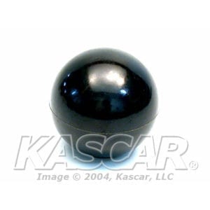
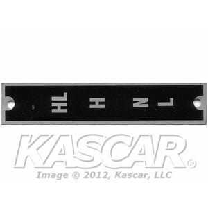
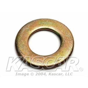
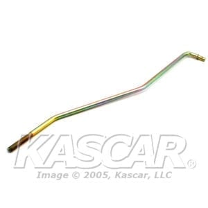
Fig. 133. Transfer Shift Controls
Last Updated On
0 out of 5 stars
| 5 Stars | 0% | |
| 4 Stars | 0% | |
| 3 Stars | 0% | |
| 2 Stars | 0% | |
| 1 Stars | 0% |
< All Topics
Item 1
SKU: 12338994
Item 2 Plate, Designation Transfer Case Position, Shift Lever Position
SKU: 12338433Plate, Designation Transfer Case Position, Shift Lever Position
$5.80
Add to cart
Item 3
SKU# 5592952
Currently Unavailable.
Call for Availability
864-422-0370
Item 4
SKU# 103384
Currently Unavailable
Call for Availability
864-422-0370
Item 5
SKU: 5593213
- (2) Required
Item 5
SKU: 5593213
- (2) Required
Item 6
SKU: 12338460
Item 7
SKU# MS16624-1062
Currently Unavailable
Call for Availability
864-422-0370
Item 8
SKU# 10L18F
Currently Unavailable
Call for Availability
864-422-0370
Item 8
SKU# 10L18F
Currently Unavailable
Call for Availability
864-422-0370
Item 9
SKU: MS24665-283
Item 10
SKU: 12338448
Item 11
SKU: 12338442-1
Item 12
SKU: 455675
Item 13
SKU: 12340565
Item 14
SKU: 12338459
Was this article helpful?
0 out of 5 stars
| 5 Stars | 0% | |
| 4 Stars | 0% | |
| 3 Stars | 0% | |
| 2 Stars | 0% | |
| 1 Stars | 0% |
5

