-
HMMWV
-
-
- Fig. 2. Engine Mounting Brackets.
- Fig. 3. Engine Oil Dipstick and Tube Assembly.
- Fig. 4. Engine Oil Pan, Pump, and Filler Tube.
- Fig. 5. Engine and Transmission Oil Cooler and Lines.
- Fig. 6. Oil Filter, Adapter, and Oil Line Fittings.
- Fig. 7. Crankcase Depression Regulator Valve
- Fig. 8. Air Intake and Exhaust Manifolds.
-
- Fig. 10. Fuel Injection Pump and Fuel Filter Lines
- Fig. 11. Fuel Injector Supply and Return Lines
- Fig. 12. Air Cleaner, Air Horn, and Related Parts.
- Fig. 13. Fuel Tank Supply & Return Lines (Early Models)
- Fig. 14. Fuel Tank Supply & Return Lines (Current Models)
- Fig. 15. Fuel Tank Assembly, Basic & A1 Trucks
- Fig. 16. Fuel Tank Assembly, A2 Trucks
- Fig. 17. Fuel Filter Pipe Assembly and Vent Lines
- Fig. 18. Fuel Tank Vent Line, Filter, And Mounting Hardware
- Fig. 19. Fuel Filter, Water Separator And Mounting Hardware
- Fig. 21. Accelerator Controls And Hand Throttle.
- Fig. 22. Accelerator Cable Bracket And Idle Spring
- Fig. 9. Fuel Pump and Mounting Hardware.
-
- Fig. 26. Radiator And Mounting Hardware
- Fig. 27. Surge Tank And Related Parts
- Fig. 28. Radiator Shroud And Related Parts
- Fig. 29. Radiator Hoses And Related Parts
- Fig. 30. Thermostat, Water Crossover & Hardware
- Fig. 31. Water Pump & Hardware
- Fig. 33a. Idler Pulley, Tensioner, Parts (SN 196901 & Above)
- Fig. 33b. Idler Pulley, Tensioner, Parts (SN 196901 & Above)
- Fig. 34. Fan Drive And Pulley
-
- Fig. 35a. Generator, 60 AMP, Belts, Pulley, and Mounting Hardware (1 of 2)
- Fig. 35b. Generator,100 AMP, Belts, Pulley, and Mounting Hardware (2 of 2)
- Fig. 44. Starter Motor, Cable Assemblies, & Hardware
- Fig. 46. Instrument Panel Assembly & Mounting Hardware
- Fig. 47. Instrument Cluster Assembly
- Fig. 48. Circuit Breakers
- Fig. 49. Directional Unit, Protective Control Box, & Flasher
- Fig. 50. Transmission Control Module, Circuit Breaker, & Relay
- Fig. 51. Stoplight Switch, Time Delay & High Beam Switch
- Fig. 60. Front Composite Light And Mounting Hardware
- Fig. 61. Rear Composite Light and Mounting Hardware
- Fig. 62. Blackout Lamp And Headlight Assembly
- Fig. 63. Clearance Marker Light Assembly
- Fig. 66. Sending Units
- Fig. 66a. Fan Cut-Off, Throttle Position & Engine Speed Sensor
- Fig. 67. Fuel Pressure & Level, & Assorted Indicator Switches
- Fig. 68. Horn And Horn Button Assembly
- Fig. 69. Batteries,Cables,And Related Parts
- Fig. 71. Battery Mounting Components & Related Parts
- Fig. 83. Body Wiring Harness-Partial View
- Fig. 84. Body Wiring Harness-Partial View
- Fig. 85. Body Wiring Harness-Partial View
- Fig. 86-1. A2 Body Wiring Harness
- Fig. 86-2. A2 Body Wiring Harness
- Fig. 88-1. A2 Body Wiring Harness Installation
- Fig. 88-2. A2 Body Wiring Harness Installation
- Show all articles ( 11 ) Collapse Articles
-
- Fig. 100. Transmission Shift Controls And Modulator
- Fig. 101. Transmission Shift Lever, Shift Bracket,And Rod
- Fig. 103. Transmission Hardware, Dipstick & Tube Assembly
- Fig. 104. Transmission Assembly
- Fig. 105. Transmission Assembly
- Fig. 123. Transmission Vent Lines And Attaching Hardware
- Fig. 124. Transmission/Transfer Cooling Lines
- Fig. 125. Transmission/Transfer Cooling Lines
- Fig. 97. Transmission Shifting Components
- Fig. 98. Transmission Shift Control And Neutral Start Switch
- Fig. 99. Transmission Shift Control And Neutral Start Switch
-
- Fig. 128. Transfer Case Assembly, P/N 12340073-1
- Fig. 129. Transfer Case, 5937387, 12342643-1, & 12447125
- Fig. 130. Transfer Case, P/N 5937387,12342643-1,& 12447125
- Fig. 131. Transfer Oil Cooler Assembly
- Fig. 132. Transfer Shift Mechanisms
- Fig. 133. Transfer Shift Controls
- Fig. 134. Transfer Shift Controls
- Fig. 135. Transfer Case Vent Lines And Related Parts
-
- Fig. 138. Front Halfshaft Assembly
- Fig. 139. Front Halfshaft Assembly
- Fig. 140. Front Axle Differential, Mounting Bracket, & Hardware
- Fig. 141. Front Axle Differential And Geared Hub Vent Lines
- Fig. 142. Front Knuckle And Geared Hub Assembly
- Fig. 143. Front Knuckle And Geared Hub Assembly
- Fig. 144. Front Control Arms, Ball Joints & Mounting Hardware
-
- Fig. 145. Rear Halfshaft Assembly, Left and Right Side
- Fig. 146 Rear Halfshaft Assembly, Left and Right Side (A2 Trucks)
- Fig. 147. Rear Axle Differential, Mounting Brackets, & Hardware
- Fig. 148. Axle Differential
- Fig. 149. Rear Axle Differential and Geared Hub Vent Lines
- Fig. 150. Rear Knuckle And Geared Hub Assembly
- Fig. 151. Rear Knuckle And Geared Hub Assembly
- Fig. 152. Rear Control Arms, Ball Joints, And Mounting Hardware
-
- Fig. 153. Parking Brake Hand Lever And Cable
- Fig. 154. Parking Brake Rod And Related Parts
- Fig. 155. Parking Brake Cables And Mounting Hardware
- Fig. 156. Parking Brake Caliper, Rotor, And Mounting Hardware
- Fig. 157. Rear Parking Brake And Caliper Assembly
- Fig. 159. Front Service Brake Lines And Proportioning Valve
- Fig. 161. Rear Brake Lines And Fittings
- Fig. 163. Master Cylinder Assembly
- Fig. 165. Service Brake Pedal Assembly
-
- Articles coming soon
-
- Fig. 169. Steering Column, Wheel, And Intermediate Shaft
- Fig. 170. Steering Linkage
- Fig. 171. Power Steering Gear And Mounting Hardware
- Fig. 174. Power Steering Pump, Pulley, And Mounting Hardware
- Fig. 175. Power Steering Pump, Pulley, And Mounting Hardware
- Fig. 177. Power Steering And Hydro-Booster Hydraulic Lines And Fittings
- Fig. 178. Power Steering Oil Cooler, Hydro-Booster, & Fan Clutch Lines And Fittings
-
- Fig. 196. Body Mounting Components
- Fig. 197. Body Assembly Components, Left Hand
- Fig. 198. Body Assembly And Related Parts
- Fig. 199. Body Assembly Components, Right Hand
- Fig. 202. Hood Assembly And Mounting Hardware
- Fig. 203. Hood Assembly Grille And Related Parts
- Fig. 205. Left Hand Splash Shield, Radiator Side Armor, And Hood Prop Rod
- Fig. 206. Right Hand Splash Shield And Radiator Side Armor
- Fig. 208. Engine Access Cover Assy, “A” Pillar Insulation, & Steering Wheel Lock
- Fig. 225. Windshield Assembly, Folddown
- Fig. 225. Windshield Assembly, Folddown
- Fig. 226. Windshield Assembly, Ballistic
- Fig. 227-1. Interior Tunnel, Cowl, Floor Insulation, Mounting Components (Foam), And Exterior Insulation (Sheet 1 of 2)
- Fig. 227-2. Interior Tunnel, Cowl, Floor Insulation, Mounting Components (Foam), And Exterior Insulation (sheet 2 of 2)
- Fig. 231. Commander’S Seat, Driver’S Seat, And Related Parts
- Fig. 234. Front Seat Belts, Brackets, And Mounting Hardware
- Fig. 235. Seats And Belts, Rear
- Fig. 239. Rear Seatbelts, Brackets, And Mounting Hardware
- Fig. 266. Tailgate Assembly And Related Parts
- Fig. 268. Cargo Shell Door, Insulation, Intermediate Pillar, Gas Spring, And Related Components .
- Fig. 270. Cargo Shell Mounting Components
- Fig. 271. Cargo Shell Assemblies
- Fig. 279. Gunner’S Platform Assembly And Mounting Hardware
- Fig. 280. Crew Door Assembly, Front, Ballistic
- Fig. 281. Crew Door Assembly, Rear, Ballistic
- Show all articles ( 10 ) Collapse Articles
-
- Articles coming soon
-
- Fig. 321. Four Man Crew Soft Top Enclosure, Bows, And Mounting Components
- Fig. 327. Windshield Wiper Motor, Wiper Assembly, And Washer Bottle
- Fig. 329. Split Rearview Mirror and Mounting Hardware
- Fig. 330, Reflectors
- Fig. 331. Diverter Assembly, Defroster, and Heater Ducting.
- Fig. 332. A2 Diverter Assembly, Defroster, Heater Ducting, and Radio Brackets.
- Fig. 333. Heater Assembly, Water Valve, and Controls.
- Fig. 352. Sun Visor Assembly and Mounting Hardware.
- Fig. 354. Data Plates, Dash Panel.
- Fig. 355. Data Plates, Battery Cable and Slave Receptacle.
- Fig. 398. Deep Water Fording Kit, Intake and Exhaust Systems.
- Fig. 399. Deep Water Fording Kit, Selector Valve, Sensor Cup, and Vent Lines.
- Fig. 400. Deep Water Fording Kit, Hydro-Boost Vent Line, Engine and Transmission Dipstick, and Tube Assemblies
- Fig. 401. Supplemental Deep Water Fording Kit.
- Fig. 402. Troop Seat Kit, Safety Strap, and Mounting Hardware.
- Fig. 403. Troop Seat Assembly, Left and Right.
- Fig. 432. Rearview Mirror Mounting Kit.
- Fig. 488. Speedometer, Speedometer Drive, and Related Parts.
- Fig. 489. Air Restriction Indicator Assembly.
- Fig. 490. Air Conditioner Compressor and Mounting Hardware, M997 and M997A1 Ambulance.
- Fig. 490a. A/C Compressor, Idler Pulley, Tensioner, and Related Parts (Serial Number 196901 and Above).
- Show all articles ( 6 ) Collapse Articles
-
- Articles coming soon
-
- Articles coming soon
-
- Articles coming soon
-
-
-
- Articles coming soon
-
- Articles coming soon
-
- Articles coming soon
-
- Articles coming soon
-
- Articles coming soon
-
- Articles coming soon
-
- Articles coming soon
-
-
-
Hummer H1
-
- Articles coming soon
-
- Articles coming soon
-
- Articles coming soon
-
- Articles coming soon
-
- Articles coming soon
-
- Articles coming soon
-
- Articles coming soon
-
- Articles coming soon
-
- Articles coming soon
-
- Articles coming soon
-
- Articles coming soon
-
- Articles coming soon
-
- Articles coming soon
-
- Articles coming soon
-
- Articles coming soon
-
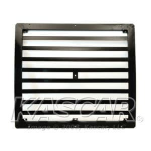
Fig. 203. Hood Assembly Grille And Related Parts
3.5 out of 5 stars
1 rating
| 5 Stars | 0% | |
| 4 Stars | 0% | |
| 3 Stars | 100% | |
| 2 Stars | 0% | |
| 1 Stars | 0% |
Maintenance
Procedures
Parts and Technical Manuals
Item 1
Item 1
Item 2
Item 2
Item 3
Item 4
Item 5
Item 6
Item 6
Item 6
Item 7
Item 7
Item 8
Item 9
Item 9
Item 10
Item 11
SKU# MS90725-6
Currently
Unavailable
Please Call for
Availability
864-422-0370
Item 11
SKU# MS90725-6
Currently
Unavailable
Please Call for
Availability
864-422-0370
Item 12
Item 12
Item 12
Item 13 Cover, Access Composite Light Cover, R.H
Cover, Access Composite Light Cover, R.H
$25.59
Item 14
Item 14
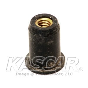
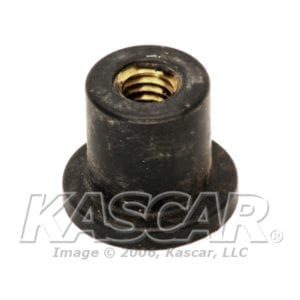
Item 15 Nutsert, 1/4-20
Nutsert, 1/4-20
$5.71 Original price was: $5.71.$4.61Current price is: $4.61.
Item 16
Item 17
Item 18
SKU# 5579485
Currently
Unavailable
Please Call for
Availability
864-422-0370
Item 19
Item 19
Item 20
Item 21
Item 22
Item 23
Item 24
Item 25
Item 26
Item 27
Item 28
Item 29
Item 30
Item 31
Item 32
3.5 out of 5 stars
1 rating
| 5 Stars | 0% | |
| 4 Stars | 0% | |
| 3 Stars | 100% | |
| 2 Stars | 0% | |
| 1 Stars | 0% |

